In this project, we will explain how to design and prototype a WiFi Controlled Robotic Car using the NodeMCU ESP8266 WiFi IoT Development Board and an L293D Motor Driver IC on a standard solderless breadboard. NodeMCU is an open-source interactive prototyping system that makes connecting hardware sensors to the internet extremely easy with simple scripting.
This mechatronics build establishes a local NodeMCU WiFi Access Point to pair with a smartphone. From there, steering commands are transmitted directly to the robot over HTTP via an Android steering application.
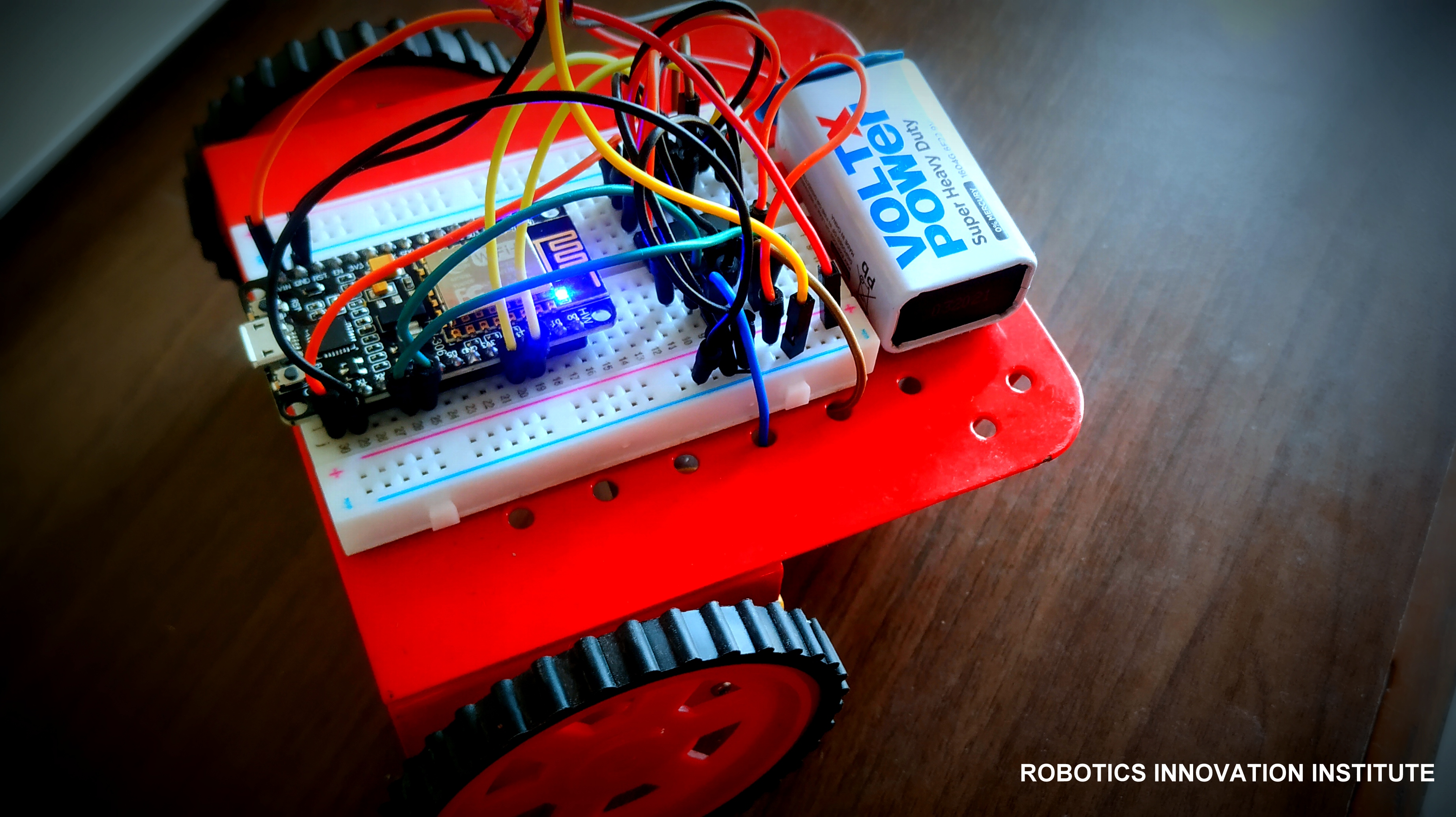
Figure 1: Complete NodeMCU WiFi IoT Robotic Car Assembly
- Local NodeMCU Access Point (AP) mode setup.
- Powerful 32-bit Tensilica LX106 core running at 80 MHz.
- L293D dual motor driver managing motor directions and PWM speeds.
- Safe solderless breadboard circuit layout.
Project Demonstration Video
Hardware Requirements
- Microcontroller: NodeMCU ESP8266 WiFi Development Board
- Motor Driver: L293D Motor Driver H-Bridge IC
- Motors: DC 3-6V BO Gear Motors & Plastic Tire Wheels
- Prototyping Platform: 400-Pin Solderless Breadboard & jumper wires
- Power Source: 9V Battery / external battery pack
- Chassis: Robotic Car Chassis kit
Core Component Deep-Dive
1. NodeMCU ESP8266 Board
The NodeMCU integration is a highly versatile IoT module built around the Espressif ESP8266 System-on-Chip (SoC). Prototyping on breadboards is effortless since it features a dual in-line package (DIP) form factor, an onboard MicroUSB programmer slot, a Tensilica Xtensa 32-bit CPU running at 80MHz, and built-in WiFi antennas.
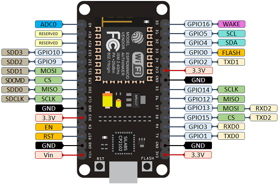
Figure 2: NodeMCU ESP8266 WiFi IoT Development Board
NodeMCU Specifications
- CPU: Tensilica Xtensa 32-bit RISC LX106 (80 MHz)
- Operating Voltage: 3.3V (Onboard 5V to 3.3V regulators)
- Digital I/O Pins: 16 GPIOs with PWM capabilities
- Analog Input: 1 ADC Pin (0V - 1V max)
- Memory: 4 MB Flash memory, 64 KB SRAM
- Wireless: IEEE 802.11 b/g/n WiFi transceiver
2. L293D Motor Driver IC
The L293D is a standard 16-pin H-Bridge motor driver chip. A single L293D IC can drive up to two bi-directional DC gear motors independently, providing continuous currents up to 600mA per channel.
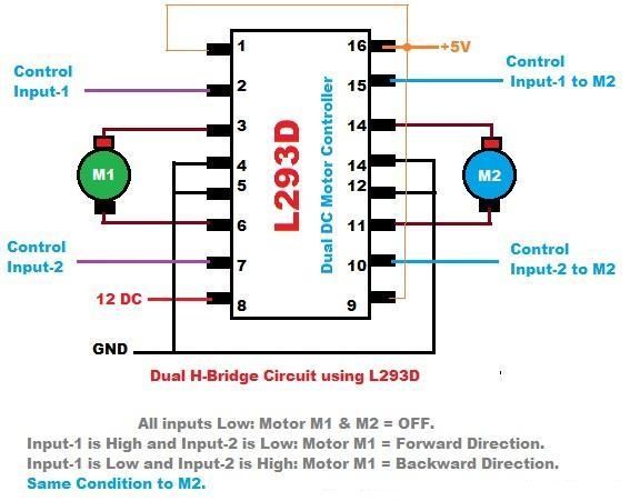
Figure 3: L293D Dual H-Bridge Motor Driver IC
L293D Specifications
- Drives up to 2 DC gear motors independently.
- Speed and direction control enabled via input/enable lines.
- Output driving voltage capacity: 4.5V to 36V
- Continuous motor currents: 600mA (1.2A brief peaks)
- Automatic thermal shutdown protection.
3. BO Gear Motor with Wheel
DC Battery Operated gear motors containing standard gearboxes to deliver high output torque for robotic wheel locomotion.
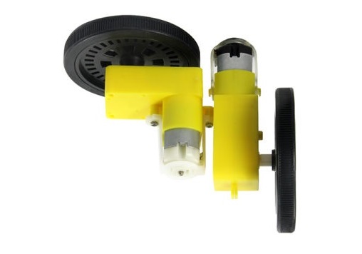
Figure 4: BO Geared DC Motor & Wheel Assembly
4. Breadboard and Chassis Platforms
Figure 5: Prototyping Robot Chassis Kit
Circuit Architecture
The NodeMCU and L293D IC are placed directly on the 400-pin breadboard. Connect NodeMCU pins D1, D2 (for Left Motor) and D3, D4 (for Right Motor) to L293D input pins. The NodeMCU 3.3V pin powers the driver logic, and a separate 9V battery connects to the L293D motor voltage supply line (Vcc2) to drive the high-current DC motors safely.
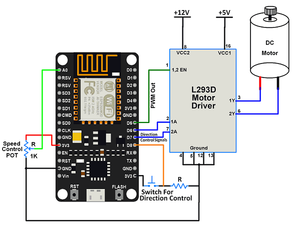
Figure 6: Breadboard Circuit Hookup Schematic
Flashing Code to NodeMCU
Follow these steps to configure your Arduino IDE to upload code to the ESP8266:
Step 1: Go to File > Preferences. Insert the custom ESP8266 boards URL into the Additional Board Manager URLs text box:
http://arduino.esp8266.com/stable/package_esp8266com_index.json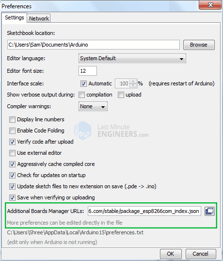
Figure 7: Copying ESP8266 Board Manager URL
Step 2: Go to Tools > Boards > Boards Manager. Search for esp8266 and click Install.
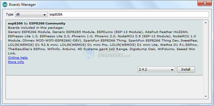
Figure 8: Installing ESP8266 Package in Arduino IDE
Step 3: Select NodeMCU 0.9 (ESP-12 Module) or NodeMCU 1.0 (ESP-12E Module) under Tools > Board.
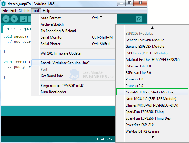
Figure 9: Selecting the NodeMCU Target Board
Step 4: Hook up NodeMCU to your computer using a micro-USB data cable. Select the assigned COM Port and set the upload speed to 115200.
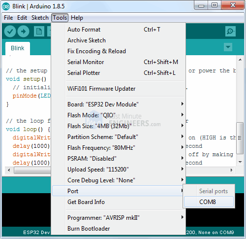
Figure 10: Assigning Serial COM Port
Arduino IDE WiFi Source Code
Copy and upload the following code to the NodeMCU module. The code runs NodeMCU in soft Access Point mode, serving a local HTTP server on port 80 to parse incoming steering requests.
// NodeMCU ESP8266 WiFi controlled Robotic Car - NextGenRoboticX
#include <ESP8266WiFi.h>
// WiFi Credentials (NodeMCU Access Point mode)
const char* ssid = "NextGen_WiFi_Car";
const char* password = "roboticscar123";
WiFiServer server(80); // Start HTTP server on port 80
// Motor driver pin connections (NodeMCU GPIO pins)
const int MotorL1 = D1; // GPIO5 - L293D Input 1
const int MotorL2 = D2; // GPIO4 - L293D Input 2
const int MotorR1 = D3; // GPIO0 - L293D Input 3
const int MotorR2 = D4; // GPIO2 - L293D Input 4
void setup() {
Serial.begin(115200);
pinMode(MotorL1, OUTPUT);
pinMode(MotorL2, OUTPUT);
pinMode(MotorR1, OUTPUT);
pinMode(MotorR2, OUTPUT);
stopRobot();
// Configure NodeMCU in Access Point Mode
Serial.print("Configuring Access Point...");
WiFi.softAP(ssid, password);
IPAddress myIP = WiFi.softAPIP();
Serial.print("AP IP Address: ");
Serial.println(myIP);
server.begin(); // Start the server
Serial.println("HTTP Server Started");
}
void loop() {
WiFiClient client = server.available();
if (!client) {
return;
}
// Read the first line of the HTTP request
String request = client.readStringUntil('\r');
Serial.println(request);
client.flush();
// Extract steering command from request (e.g. GET /forward)
if (request.indexOf("/forward") != -1) {
moveForward();
} else if (request.indexOf("/backward") != -1) {
moveBackward();
} else if (request.indexOf("/left") != -1) {
turnLeft();
} else if (request.indexOf("/right") != -1) {
turnRight();
} else if (request.indexOf("/stop") != -1) {
stopRobot();
}
// Return HTTP response
client.println("HTTP/1.1 200 OK");
client.println("Content-Type: text/html");
client.println("");
client.println("");
client.println("");
client.println("NextGen WiFi Robotic Car Controller
");
client.println("");
delay(1);
}
void moveForward() {
digitalWrite(MotorL1, HIGH);
digitalWrite(MotorL2, LOW);
digitalWrite(MotorR1, HIGH);
digitalWrite(MotorR2, LOW);
}
void stopRobot() {
digitalWrite(MotorL1, LOW);
digitalWrite(MotorL2, LOW);
digitalWrite(MotorR1, LOW);
digitalWrite(MotorR2, LOW);
}
void turnLeft() {
digitalWrite(MotorL1, LOW);
digitalWrite(MotorL2, HIGH);
digitalWrite(MotorR1, HIGH);
digitalWrite(MotorR2, LOW);
}
void turnRight() {
digitalWrite(MotorL1, HIGH);
digitalWrite(MotorL2, LOW);
digitalWrite(MotorR1, LOW);
digitalWrite(MotorR2, HIGH);
}
void moveBackward() {
digitalWrite(MotorL1, LOW);
digitalWrite(MotorL2, HIGH);
digitalWrite(MotorR1, LOW);
digitalWrite(MotorR2, HIGH);
}Google Drive Project Downloads
Download the fully validated source code files and the pre-compiled Android steering client package from our shared drives: